
Golden Scan HPE PCB / electronics repair challenges
- Jul 16, 2025
- 9 min read
Golden Scan HPE PCB: An unexpected challenge
My first restoration project here in Czechia, was a big challenge, which doubled the feeling of hopelessness, since I knew that the Golden Scan HPE worked normally when I first bought it some years ago. I typically do not plug in old fixtures, but this was an exception, as the fixtures were operating in a club here in CZ, so the owner wanted to show me that they operate properly, before my purchase.

The challenge considered the electronic PCBs only, and no matter of their simplicity, I never thought I would be kept busy for about three weeks in order to understand what exactly happens with them. I have to note that I am not professional or highly educated/certified on electronics field. All I know, is as hobbyist, from books with basics, general knowledge from technical school years, and my experience with fixtures restorations since 2011.
I was very optimistic from the beginning with this one, since it worked just fine before the restoration, in comparison with its brother, which had its challenges from the start, and this was one of the reason I decided to restore it first, moving it in Athens, so I would have all the time and space I needed to experiment. I was thinking, ‘lets leave the easy one for when I will be here in CZ, and face the challenge first’. But, it was the opposite after all.
In general, my first step with such old fixtures is to wash the PCBs after removing all the ICs and microprocessors, and dry them thoroughly immediately. This is the only way to remove such excessive dirt and dust. Especially the Golden Scans 3, all the MiniScans, and the Golden Scan HPE PCB I have restored, were way too dirty for cleaning them only with a brush. Only the PCBs from Stage Scans and Golden Spots were in pristine condition.

After the drying is complete, I remove the electrolytic capacitors, the rectifying diodes and voltage regulator, replacing them with brand new. Then, I power up the PCB and measure that all the voltages are fine, both the high for the motors, and 5V for the components. If everything is okay, I add the ICs and I connect some of my spare stepper motors, to check if the reset starts properly. Just each board only, not with the back panel DMX receiving PCB connected yet. Don’t forget that I am talking about the first version of the scanners, which had 3x PCBs. So their age is almost 30 years old now.
Each power up, and a new strange issue
In the meantime, I had the fixture’s main base with the effect modules ready. And, when I completed the installation and connection of the PCBs and I ran the first test, the chaos unleashed. Not immediately though. As the first reset completed normally into both boards, (I didn’t run the onboard test then [DIP no.10 ON]) I wanted to perform a test via DMX, and calibrate the mechanical effects, if needed (the shutter blades need always calibration). I was too optimistic that everything was all right on that point. On the second power up, both PCBs acted totally random. During the multiple repowering, one could work, while the other didn’t. One could ‘listen’ to DMX, while the other didn’t.
Apart from this type of problem, which seemed to be signal or interference related, and caused me to focus on the DMX receiving PCB, with the dipswitches, a new problem appeared on both stepper motor driving control PCBs. Periodically, they didn’t initiate the reset process after power up.

For starters, I focused on the back panel PCB, on which I replaced everything I haven’t replaced after the cleaning process. I was trying to figure out if the Microcontroller was operating just fine, so I also had to change the clock crystal and its two ceramic capacitors. The measurements with the scope showed that the MCU worked properly.
Then I focused on one of the two motor driver PCBs, trying to figure out what happens with the reset. Apart from this issue, if the PCB started the reset process, after the motors acted like they had been getting min/maximum commands, operating erratically, even when the ribbon cable was not connected on the DMX PCB anymore. It was like the boards appeared with new and random problems with one start after the other.

Reset: The biggest problem
The biggest mystery was the MCU reset, as in the first place seemed normal in the scope. The pulse seemed normal for the capacitor's original value. During the tests, (not constant observations on that point), the MCU reached a point that either the reset wouldn’t start at all, or it would interrupt the reset process and stop. If the reset was completed normally, and without any erratic movement of the motors, after a few seconds there was extreme noise/interference sound on them, and with the scope, I noticed that the new NAND gate (4093) oscillated too much. The outgoing signal from the MCU seemed normal, but the one coming out of the NAND gate had an extreme frequency.
After many tryouts on the fixture itself, I decided to completely remove the board, and test it as I did in the start. Alone, without the DMX board, in my office, with the test motors. I also removed the old ribbon cable completely.
On that point, I have to mention that all the capacitors related to the MCU part were replaced. Electrolytic, ceramic and film capacitors. Only the resistors and one 1N4148 diode remained the original.

To my surprise, the noise on the motors stopped after removing the ribbon cable, and testing it out of the fixtures, making me think if it is possible for the old cable to cause such interferences, even if it wasn’t connected anywhere. (the abnormal behaviour appeared also periodically when the connection with the DMX PCB was present).
In the meantime, I have ordered the original NAND gate, the HEF 4093 BP, just to be sure, as the original with the new ones, had different parameter thresholds. Also, on that point, I still wasn’t sure if the Microcontrollers worked properly, so I was preparing myself mentally for the possibility that maybe I will not be able to work with this light. I was always hopeful, and the cause of my presistance was that both the MCUs showed the same behaviour when swapped on the PCBs. At that time, I had to replace the crystals and capacitors as well, as I guessed that the freeze could be caused by a faulty / worn out crystal. But it was the reset circuit, always, as you will read below.
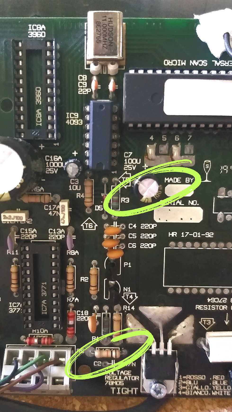
Since the issue with the abnormal behaviour of the motors had -temporarily- vanished, I wanted to observe the reset function of the PCB. The reset circuit contains a capacitor of 25V, 100uf connected to 5V, while its negative is connected to Pin number 9 of the MCU, and a 10K resistor. The resistor is connected to the ground. Pretty simple circuit.
Observing the connection on Pin 9 with the scope, I noticed the pulse, and then the discharge of the cap to almost zero voltage. But after a couple of seconds, sometimes minutes, the period is totally random, there are fluctuations on this signal, which if it passes above a certain level, the MCU will enter a reset phase, or freeze. This is what happens most of the time. I checked all the ground connections and resoldered the resistor points.
For the reset matter, in one PCB it seems that the problem is resolved with resoldering the resistor (fluctuations still exist, but they are not high enough to freeze the MCU), and for the other PCB, I replaced the resistor, which didn’t solve the problem immediately, so I experimented by adding another parallel resistor of a lower value (than the original 10K). This seems to keep the fluctuations low enough. I am still sceptical about the reason of this since I have in mind two parameters:
The ground is common on the motor driver PCBs, it is interconnected on the back panel (DMX receiving PCB), and there, it is also grounded (connected directly on the earth cable from the network).
I was thinking about Cyberlights, as they use isolated ground for the DMX circuit, and different ground for the MCU and other ICs, avoiding a common connection with the motor drivers, for better isolation probably. So I was thinking about the possibility that the fluctuations are caused because of the motor drivers and the ground was not connected on the earth cable during the tests.
In any case, the reset worked fine on that point, but another problem re-appeared: the erratic operation of the motors. I was touching the components near the MCU, trying to see if anything was warm and so on. When I touched the small 1N4148 diode, the erratic behaviour stopped. Letting it reappeared, touching, pressing it softly, stopped.

This component, together with resistors and ceramic caps, to my understanding, are responsible for the MCU's function either with digital DMX data, or the analogue input. I was experimenting with the behaviour of the PCB without these components, including the two transistors NPN and PNP, which are not included on newer PCB versions (those without analogue connections). Without this group, the PCB didn't received the commands from the DMX receiving PCB. neither DMX, or test command from the dip switch.
Replacing all the components on this circuit (transistors, diode and ceramic caps -excluding the resistors-) the PCB worked satisfyingly well. I connected it also with the DMX receiving PCB, on which I had replaced nearly everything, and it worked smoothly. The test process could be started, by activating the dip no. 10 on the address dip switch.
Regarding the reset issue, both PCBs continued to have fluctuations on Pin 9, but on the one, with the original resistor they are remaining low and at a safe level. On the other PCB, I probably need to keep the parallel resistor connected (without knowing if this really plays a role), as the issue could occur at totally random times and random time intervals.
Now, both PCBs are connected with the DMX PCB and installed in the fixture, and work fine. At least in all my current tests yet. I will continue testing, also without the extra resistor, as I have it 'on the fly' as you may notice on the video. The mystery with the reset circuit is not entirely resolved, at least it hasn’t reappeared in my last tests for calibration and using the fixture with DMX, and it is the first time I have to deal with such issues on the Pulsar's PCBs, as they have proven to be so durable and real work horses. Even the older in age, and much worn PCBs from the Golden Scans 3, didn't give me such a challenge.
In any case, this is a reason to be happy, as since the microcontrollers operate properly, there is nothing else to keep me from making the PCBs work, even if I had to replace everything on them. Also, if the firmware was available, there would be no worries at all, since the same microprocessors can be found on the market, and they could be programmed with the same firmware version.
Summer holidays are getting closer, so my long desired second Golden Scan HPE (the model I firstly saw on a brochure as a teenager) will be ready to light from September possibly.
I have a plan to almost completely renew their gobo palette, keeping 3 classic metal gobos, and replacing the rest, with nice, more modern breakups, and patterns suitable for rotation, adding the HD photographic rose gobo, and one unique glass. Also, I will replace two color filters, one of them is the 4-color one which I never use. I am planning to use two light accent filters, one of lavender and another of green, which will help in the creation of more color shades, getting an example of the Golden Spot amazing deep color combinations.
With this blog post, I want to wish you to enjoy the rest of your summer, full of shows, restorations, or holidays!


![[Update!] The page about first Euroscan generation restoration and history behind it, is updated!](https://static.wixstatic.com/media/2d0121_8ab01edd00534930a32ce46d32759080~mv2.jpg/v1/fill/w_1000,h_1000,fp_0.50_0.50,q_30,blur_30,enc_avif,quality_auto/2d0121_8ab01edd00534930a32ce46d32759080~mv2.jpg)
![[Update!] The page about first Euroscan generation restoration and history behind it, is updated!](https://static.wixstatic.com/media/2d0121_8ab01edd00534930a32ce46d32759080~mv2.jpg/v1/fill/w_296,h_296,fp_0.50_0.50,q_90,enc_avif,quality_auto/2d0121_8ab01edd00534930a32ce46d32759080~mv2.jpg)


![Golden Scan HPE [the 2nd]: Reborn completed!](https://static.wixstatic.com/media/2d0121_6de1e0a6a0f540479626764a0c5bd1c9~mv2.jpg/v1/fill/w_1762,h_1000,fp_0.50_0.50,q_30,blur_30,enc_avif,quality_auto/2d0121_6de1e0a6a0f540479626764a0c5bd1c9~mv2.jpg)
![Golden Scan HPE [the 2nd]: Reborn completed!](https://static.wixstatic.com/media/2d0121_6de1e0a6a0f540479626764a0c5bd1c9~mv2.jpg/v1/fill/w_296,h_168,fp_0.50_0.50,q_90,enc_avif,quality_auto/2d0121_6de1e0a6a0f540479626764a0c5bd1c9~mv2.jpg)


Comments